Racing the Beam
This post is the fourth in a series looking at the design and implementation of my Glitch demo and the m4vgalib code that powers it.
In part three we took a deep dive into the STM32F407’s internal architecture, and looked at how to sustain the high-bandwidth flow that we set up in part two.
Great, so we have pixels streaming from RAM at a predictable rate — but we don’t have enough RAM to hold an entire frame’s worth of 8-bit pixels! What to do?
Why, we generate the pixels as they’re needed, of course! But that’s easier said than done: generate them how, and from what?
In this article, I’ll take a look at m4vgalib’s answer to these questions: the rasterizer.
Making my life difficult
I’ve gotten some reader feedback from the earlier parts of this series1 — mostly positive, thanks!
What? People read my blog? Who are you people‽
But one question comes up often enough that I feel like I ought to address it here. It goes something like this:
Why did you pick the STM32F407 when [other chip name here] has more RAM, video hardware, and/or can also be used as a dessert topping?
It’s a great question, with an odd answer.
I picked the STM32F407 for this project, not because it was easy, but because it was hard.
I like weird graphics chipsets, but I was born late enough that I never had an Amiga or an Atari ST. Indeed, I was born into an all-PC household, which (even though it turned out to be useful professionally) is about the most boring hardware ever put into a home computer.
Around 2009, microcontrollers2 became powerful enough to start doing interesting video in software. And my definition of “interesting” is heavily influenced by my PC background: I remember the day I first got my hands on a Paradise VGA card and was able to push my PC into 800x600 (and all of 16 colors). High resolution was a game changer, so I set my sights high for my own projects.
Yeah, you could generate video with something like an i860 dating back into the late 80s. I’m admittedly limiting my focus to chips that (1) have an open toolchain and (2) are the sort of chip I could easily build a board around.
There is a dark side to using a chip with built-in video hardware: you’re limited by whatever applications its designers imagined. Consider the STM32F427, the ’407’s big sister. It can drive 800x600 natively from its built-in LCD controller.
But it only does raster graphics from RAM. To draw a 256-color image, like the ones Glitch uses, you’ve gotta add around a megabyte of memory. There’s no character graphics mode, no line doubling, no sprite engine, no ability to change video parameters at scanline boundaries to do split-screen or raster effects. And there’s certainly no polygon rasterization and clipping engine!
In short, it’s both too powerful to be interesting, and not powerful enough to be fun.
Conversely, the fun thing about doing video in software is that so few decisions are made for you. Your imagination is the only limit to the architecture.
256-color character graphics in only 11k of RAM? Go for it.
Want 256-color 3D graphics driven by a display list? Write the code.
In the fall of 2012, I analyzed the capabilities of the STM32F407, and decided that it was barely powerful enough to do what I wanted. Which is perfect.
In part three I wrote in some detail about the bandwidth constraints of the STM32F407’s interconnect and how I worked around them. In the next two sections I’ll cover the remaining two constraints — space and time — and then take a look at how I’m playing within them.
Space constraints
In the previous two parts of this series, we looked at the output stage of m4vgalib’s graphics pipe, which can generate a screen of up to 800x600 pixels at 8 bits each.
Some multiplication will show that storing all of those pixels would take 480,000 bytes of RAM. The STM32F407 has 196,608 bytes of RAM. We can produce a much bigger image than we can store3!
Of course, such an image would fit in Flash on the STM32F407, and it is possible to display a static image from Flash with m4vgalib — but moving pictures are far more interesting, so that’s the last I’ll say of that.
This problem has plagued computer graphics since the beginning. There are three traditional ways of dealing with it:
- Reduce depth (quantize).
- Reduce resolution.
- Find a different representation (i.e. not pixels).
Reducing Depth
m4vgalib’s output stage produces 8-bit pixels, but there’s no particular reason why we need to store 8-bit pixels. We could store only 4-, 2-, or 1-bit pixels, and translate them to 8-bit pixels using a palette.
Using 4-bit pixels, an 800x600 display would still require more RAM than we have
(240,000 bytes), but with 2-bit pixels, we can manage it — and with 1-bit
pixels we can afford two screens, for double-buffering. (This is why the
rook and conway demos use two colors: they need to double-buffer a
complete framebuffer and must reduce depth.)
Reducing Resolution
We can also reduce the RAM requirement of the display by reducing the number of pixels we store. At 640x480 we still can’t afford a full screen of 8-bit pixels, but we can afford a screen of 4-bit pixels (just barely).
Leaving the monitor at 800x600, we can also reduce the effective resolution by drawing each “pixel” as a square or rectangle, made up of several real pixels. m4vgalib distinguishes between stretching pixels horizontally (reducing X resolution) and repeating entire lines more than once (reducing Y resolution), but they’re similar concepts.
If we reduce the resolution on both axes by a factor of 4, we end up with a
display made of 200x150 very chunky pixels. In this mode, a full screen of
8-bit pixels takes only 30,000 bytes — we can easily afford to store two of
these in RAM! (The rotozoom demo uses this mode.)
Using a different representation
There’s no intrinsic reason why we need to store pixels at all. Yes, the output stage needs to find some pixels in RAM, but we could incrementally produce pixels from some more compact representation.
For example, displays ranging from old vector displays up through modern 3D accelerators store content in display lists — arrays of drawing commands that get played out each frame. When doing this in software, it’s a classic time-space tradeoff: the display list can take far less space than the pixels it describes, but we need to execute the commands specified by the list on every scanline or frame. (None of the published demos use this technique, but you can see a couple seconds of it in Glitch: the rotating cube is drawn this way.)
As a special case of the display list, older computers had dedicated character
graphics (or text) modes. Even more restrictive than a display list, in
character graphics modes, the computer could only show characters on a fixed
grid. But all it needs to store are characters, and maybe a font to describe
how to draw them — which is way more compact than storing the pixels that are
produced. (The hires_text demo uses a character graphics mode and can fit
14 screens in RAM.)
Hybrid approaches
Of course, none of these techniques are mutually exclusive. We could simultaneously reduce the depth and resolution, for example.
In early computer graphics it wasn’t uncommon to split the screen, running a
more expensive mode on part of the screen, while filling the rest with a
cheaper mode. If you played any flight simulators during the 1980s, you might
remember a huge instrument panel topped with a tiny sliver of window to the
outside world; now you know why. (The rook and wipe demos both do
this.)
The choice is yours
So which of these options does m4vgalib choose? Well, none of them, really — or all of them. They’re all great ways of doing things, so I left the options open to applications.
Within the time allowed, that is.
Time constraints
I like to visualize cyclic periodic tasks — like producing a scanline of video — using a sort of diagram. I call this a “clock diagram,” because (like a clock) it shows time advancing clockwise in an endless circle. Instead of 12 or 24 hours, this circle covers only 26.4 microseconds.
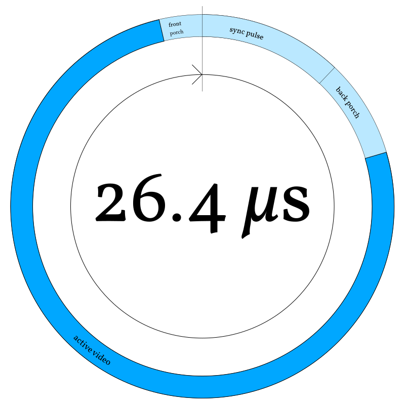
At the top of the circle (midnight), the horizontal sync pulse begins4, followed by the back porch. Active video (scanout) begins at about 2:30 and continues until around 11:30, when the next horizontal blanking interval starts with the front porch. (These “porch” terms are not my invention; they were named by analog television engineers, who apparently like weird metaphors.)
Why is midnight on this clock the beginning of the sync pulse, rather than the beginning of the blanking interval? Because that’s how m4vgalib’s horizontal timer is actually set — timer rollover begins the sync pulse.
It’s important to stay conscious of this cycle of timing. Video generation is a hard real-time problem: late pixels are as bad as no pixels at all, because they visibly distort the display.
Every scanline, at the start of active video, the DMA scanout process begins anew. At this point, we either need to have a scanline’s worth of pixels ready to go in RAM, or we need to be prepared to generate them faster than they’re consumed — to race the beam.
It turns out that we really want to do both, to dodge two problems with the simplest way of racing the beam: it turns out we have both too much and too little bandwidth to do that reliably.
Too much bandwidth (on the output)
Literally racing the beam5 is pretty hard in this system, because — as I discussed in part two — the pixel clock is exactly ¼ the CPU clock. To beat the beam, you’d have to spend four cycles or less on each pixel. The Cortex-M4 core at the heart of the STM32F407 can do a pretty impressive amount of work per cycle, but that’s pushing it.
Okay, if you want to be pedantic, literally racing the beam is pretty hard because modern displays don’t have a “beam” — that refers to the electron beam that drew the display in older CRT monitors. But since modern displays try their hardest to simulate a CRT, we’re now literally racing a metaphorical beam. ;-)
m4vgalib works around this by generating pixels ahead of the beam by one line. The scanout reads from one buffer, while the next line of pixels are deposited in another. This lets us generate pixels during the entire scanline, including hblank; at 800x600 this gives us 5.28 cycles/pixel, instead of just 4. That extra 1.28 cycles can mean a lot.
Not enough bandwidth (in the AHB matrix)
Even if you can generate pixels into the DMA buffer fast enough to keep ahead of scanout, doing so is dangerous, as I discussed in part three: writing to the scanout RAM while DMA is in progress causes a matrix conflict, which steals cycles from the DMA flow and can corrupt the displayed image.
m4vgalib avoids this by writing pixels into a separate SRAM from the one used
by DMA. It would be reasonable to flip SRAMs each line: write pixels into SRAM2
while DMA reads SRAM1 on line N, then write pixels into SRAM1 while DMA reads
the result from SRAM2 on line N+1. However, the STM32F407 just doesn’t lend
itself well to this approach, because the SRAMs are so asymmetrical (16k and
112k). By scanning out of SRAM1 on every other line, we’d lose access to the
vast majority of our RAM half the time — or risk corrupting the video by
accessing it.
Instead, and perhaps counter-intuitively, m4vgalib always writes pixels into
CCM, and always streams out of SRAM2. At the very beginning of hblank, the
driver copies the pixels from CCM to SRAM2. This costs a small amount of CPU,
but since the Cortex-M4 can shuffle data around quite quickly, it has less
overhead than you might expect6. m4vgalib’s heavily optimized
copy_words
routine
comes tantalizingly close to the theoretical maximum throughput of the AHB
matrix — it runs about twice as fast as the DMA hardware.
You might expect me to use DMA to copy this data: it happens during
hblank, so GPDMA2 — the only DMA controller that can transfer
memory-to-memory — is available. The copy could overlap with
generation of the next line, potentially saving some time…or so it
seems.
I’ve tried this, and discovered something unexpected: it’s slower,
by quite a bit. Not only can my tuned copy_words routine outrun
the DMA controller by 2x, doing the copy with the CPU before
rasterizing uses less overall time than doing the two concurrently,
due to conflicts.
Rasterizers to the rescue
m4vgalib refers to this entire topic as rasterization: the process of decoding some representation of an image into pixels, one line at a time, so that they can be streamed by the output stage without delay.
Since m4vgalib is designed to mimic late 80s and early 90s graphics hardware, it could provide a bunch of canned resolutions and modes that applications could choose between. But m4vgalib isn’t hardware, and we don’t have to be so rigid. Instead, a pluggable component called a rasterizer makes most of the interesting decisions. m4vgalib includes a bunch of example rasterizers, but applications can provide their own.
What’s a rasterizer?
A rasterizer is simply an object whose class implements the vga::Rasterizer
virtual interface. Its job is to make some pixels whenever m4vgalib says so.
“Make some pixels” happens to be the only operation on the vga::Rasterizer
interface; we call it rasterize:
;
A rasterizer gets called with the line_number being drawn on the display
and a place to deposit pixels in RAM, the raster_target.
The rasterizer does its thing, and then returns7 a RasterInfo
struct describing what it did. I’ll pick RasterInfo apart later in this
article.
Remember, returning structs like this in C++ is cheap and safe even in high performance code, thanks to the return value optimization. In any modern calling convention it’s no costlier than passing a pointer to a temporary.
If this interface looks generic, that’s because it was designed to be. m4vgalib doesn’t care how the pixels get made, only that they’re ready when it needs them. To see some of the flexibility of this model, consider the example rasterizers included with either m4vgalib or the m4vgalib demos:
- Processing 1bpp bitmap images with a two-color palette.
- Generating a color procedural texture with smooth-scrolling.
- Combining ASCII text with a font to produce colored character graphics.
Glitch has a few modes that I haven’t yet published, including full-screen solid polygon rendering in a rasterizer. Rasterizers are the really fun part of working with m4vgalib — your imagination, and CPU throughput, are the only limits.
When does a rasterizer get called?
Here’s the cycle of events, overlaid on the clock diagram from the last section.
m4vgalib arranges for an interrupt to fire at the beginning of hblank, called
end_of_active_video (in red at around 11:30). This interrupt does some
housekeeping and then arranges for three things to happen, in this order:
-
The pixels for the next line of video are copied into scanout RAM (as discussed a few sections ago; in purple at 11:45).
-
If the application defines a
vga_hblank_interruptfunction, it gets called from an interrupt (turquoise, around midnight). -
The rasterizer gets called from an interrupt (light purple, starting around 00:15).
This order is significant because the first two things — the line copy and the hblank interrupt — must happen inside hblank, but the rasterizer can safely overlap with active video. So the rasterizer gets called last.
The fact that the rasterizer is called from an interrupt is also important. Even though the rasterizer is (or can be) part of the application, the application does not need to run its main loop at the horizontal retrace frequency. It can configure a rasterizer (using a mechanism to be presented shortly) and then kick back and produce data for the rasterizer to consume at whatever rate is appropriate. Note that in the diagram, the application main loop (green) is preempted by this interrupt activity (zebra stripes).
m4vgalib does not call the rasterizer — or the application hblank handler
— directly from end_of_active_video. With all due respect, it does not
trust any user-provided code to meet its latency constraints. Instead, it uses
a peculiar feature of the ARMv7-M architecture: the PendSV
interrupt8.
I’d love to provide a convenient link to ARM’s discussion of this interrupt, but I’m not sure it’s possible — ARM’s reference site is really hard to link into. Go Google “PendSV” if you’re curious.
PendSV is a software interrupt like the x86 int or ARM svc instructions,
but it’s an asynchronous software interrupt. There’s no way to trigger it
synchronously like a system call, but there is a way to pend it so that it
executes later, whenever interrupt priorities allow9.
Sure, you can do this with basically any interrupt. The weird thing about PendSV is that it’s explicitly intended for this. This feature is unique among the architectures I know.
In the case of m4vgalib, PendSV is configured to be lower priority than all the latency-sensitive horizontal timing interrupts — among the priority rings in the diagram, it’s priority two. In the end-of-active-video ISR, m4vgalib pends PendSV (the inward-pointing arrow). This means:
- The PendSV handler will run after the higher-priority interrupts are done.
- The higher priority interrupts can interrupt PendSV later if needed.
That second point is very important. A typical rasterizer will take most of the scanline to finish, but the start-of-active-video interrupt needs to happen at the end of hblank (around 2:30 in the diagram). Because the rasterizer runs at PendSV priority, m4vgalib can briefly interrupt it to start DMA, using the “shock absorber” (from part three) to ensure deterministic latency.
Now, should a rasterizer still be running by the time the next hblank starts,
end_of_active_video preempts it, pausing its execution. This ensures that the
display remains stable even if the rasterizer is buggy. (There’s even a case
where you might do this deliberately; I’ll discuss it below.)
Combining rasterizers
One of the things I really like about the Atari ST and Amiga video chipsets is their ability to change modes, if desired, at each scanline — so of course I had to include support for this in m4vgalib.
Applications can choose a single rasterizer to handle the whole screen if needed — but m4vgalib also allows different rasterizers to handle different parts of the screen.
m4vgalib records all this in a linked list of structures, each of which
describes a band of adjacent scanlines. Each record is called a Band (from
vga.h in
m4vgalib):
;
Bands can be any size — as small as a single scanline.
Applications hand m4vgalib a list of bands using vga::configure_band_list
function.
Applications can adjust band boundaries, or provide an entirely new band list,
at each vertical blanking interval — any changes through configure_band_list
take effect just before the first non-blank line of the frame. This allows
clean transitions from one mode to another, but it also means you can animate
the boundary between rasterizers if desired.
Some examples from the demos:
conwayuses a single band covering the whole screen.rookuses several bands to mix pixel and character graphics, but also save CPU usingSolidColor(discussed below).wipeuses a simple band list but rewrites it dynamically to produce an animated split screen effect.
Doing more with less: RasterInfo
Whenever a rasterizer runs, it returns a RasterInfo struct describing the
result. RasterInfo consists of four fields:
;
This describes the pixels that the rasterizer generated into the
raster_target, and — more importantly — provides instructions from the
rasterizer about how these pixels should be put on screen:
-
offsetlets the rasterizer shift video output left to render a horizontally narrower mode — for example, a 600-pixel-wide mode in an 800x600 frame. Missing pixels to the left will be filled with black.offsetis signed so that the output can also be shifted right, which is occasionally useful for implementing cheap smooth scrolling; shifting too far right will confuse the monitor. -
lengthis the number of pixels the rasterizer deposited. Any missing pixels at the right side of the line are filled with black. -
stretch_cyclesextends the duration of each pixel in this line, in units of CPU cycles (¼ of a pixel). For example, returning astretch_cyclesvalue of 4 halves the horizontal resolution. -
repeat_linesasks m4vgalib to draw this same scanline a certain number of times before calling back into this rasterizer. This can be used to reduce the vertical resolution.
By reducing length, increasing stretch_cycles, and/or increasing
repeat_lines, a rasterizer gets away with generating fewer pixels, and thus
buys itself more cycles per pixel — at the cost of a smaller or
lower-resolution display.
By increasing stretch_cycles, the rasterizer actually lowers the rate of DMA:
m4vgalib will switch over to the slower timer-controlled DMA mode automatically,
reducing the risk of conflicts and making more AHB bandwidth available to the
application.
By increasing repeat_lines, an expensive rasterizer can actually run right
through hblank and use multiple scanlines’ worth of time10.
Support for this is slightly buggy at the moment. Hint: it doesn’t work on the top line of the display yet.
If repeat_lines would cross into a Band controlled by another rasterizer,
m4vgalib adjusts it down so the rasterizers play nice.
The most extreme example of all this is the SolidColor rasterizer, which is
short enough that we can go through all the code below.
Example: SolidColor
Let’s look at a concrete example: m4vgalib’s simplest rasterizer, SolidColor.
As its name suggests, it produces pixels of a single color. It needs to store
only a single pixel, which it will smear across the display, so it’s very cheap
in terms of RAM. It’s also very light on CPU, thanks to careful use of
RasterInfo.
Here’s the important part of SolidColor’s class definition; for the full file,
see rast/solid_color.h in m4vgalib.
;
Note that, in addition to the _color (the byte-sized framebuffer for this
simple mode), SolidColor stores a _width, so that it can interact correctly
with modes other than 800x600 — like 640x480.
The implementation isn’t much longer (excerpted from rast/solid_color.cc in
m4vgalib):
: ,
Rasterizer::RasterInfo
The RasterInfo result tells m4vgalib that…
SolidColoronly produced a single pixel,- That pixel should be stretched horizontally for the rest of the line (the 4 default clocks plus the rest), and
- The line should be repeated vertically “forever,” or close to it.
Example: Bitmap_1
For the final example in this section, let’s move from the simplest rasterizer
to one of the most involved. Bitmap_1 provides two framebuffers (for
double-buffering), each of which uses one bit per pixel. It uses a two-color
palette to turn those bits into 8-bit colors.
Of course, the palette can be changed at any time, including scanline boundaries.
Bitmap_1 is about 130 lines of C++ as of this writing, plus about 50
instructions of assembly language, so I won’t copy and paste all of it here.
Instead, I encourage you to pull up the sources and follow along:
rast/bitmap_1.h(the header file)rast/bitmap_1.cc(the C++ sources)rast/unpack_1bpp.S(the assembly sources)
The challenge in writing Bitmap_1 is unpacking bits into bytes. For each bit
in the framebuffer, we need to choose one of the two palette entries, and
deposit it into the raster_target. m4vgalib contains a few optimized assembly
routines11 for tasks like this, collectively called unpackers; Bitmap_1
uses the 1bpp unpacker, unpack_1bpp.
Along with copy_words, these are 100% of the assembly language in
m4vgalib. You don’t need to write in assembly just to get high performance;
compilers are pretty smart these days.
It’s fastest to read data from memory in 32-bit words. Knowing this, we might try to implement the unpacker in C++:
// Not actual m4vgalib code.
Pixel palette;
uint32_t const * framebuffer;
...
for
A reasonable assembly language translation of that method goes a little something like this:
    ; Not actual m4vgalib code.

    ; framebuffer is r0
    ; raster_target is r1
    ; palette is r2
    mov r3, #(800 / 4)      ; initialize loop counter in r3

0:  ldr r4, [framebuffer, r3, LSL #2]     ; load chunk into r4
    ubfx r5, r5, #0, #1                   ; extract bit zero
    ldrb r5, [r2, r5]                     ; load byte from palette
    strb r5, [r1], #1                     ; write it out, advance raster_target
    subs r3, #1                           ; decrement loop counter
    bne 0b                                ; repeat until zero
Six instructions — not bad! But, wait, six? We’ve only got four cycles per pixel, or 5.28 if we squint. A quick review of the Cortex-M4 Technical Reference Manual’s cycle time chart12 shows that we’re actually using 12 cycles per pixel, not counting setup costs!
Plus some knowledge I gained through reverse engineering — the TRM leaves a couple of details unspecified.
So this approach won’t work.
There are a variety of ways to hack around this. I tried a lookup table that processes pixels in groups of 8; this burns 512 bytes of RAM and can be quite a bit faster, but makes palette changes non-atomic and much more expensive. I found a different approach that’s just as fast without resorting to a lookup table; it relies on the Cortex-M4 integer vector instructions.
If you’re familiar with instruction set extensions like Intel’s SSE or IBM’s Altivec, the vector instructions on the Cortex-M4 will be familiar, but less powerful. Instead of operating on large (128-bit) vector registers, the M4’s instructions just operate on the normal registers, treating them as vectors of integers — either a pair of 16-bit numbers, or four 8-bit numbers. In this code, I use the four-byte mode exclusively. I’ll refer to the byte positions within registers as byte lanes.
Of particular interest here is the sel instruction. sel is intended to
combine the results of two computations, selecting one or the other, sort of
like a conditional mov. But unlike mov, sel operates independently on
each byte lane.
Just like conditional mov, sel decides which input to select based on flags
in the processor’s status register (APSR). But sel needs four independent
flags, not a single flag — so instead of (say) the carry bit, sel uses the
four GE flags.
The GE flags are normally set by vector operations. If you add two
four-vectors using the uadd8 instruction, the carry bits of each of the four
additions wind up in the GE flags, one for each byte lane.
What does this have to do with bit unpacking, you ask? Well, with sel, the
GE flags act as a four-wide bit-controlled multiplexer. And while it’s not
terribly obvious from the instruction set specification, we can directly write
the GE flags. The following instruction moves bits 19:16 of r0 into
GE[3:0]:
msr APSR_g, r0
By transferring bits from the framebuffer into the GE flags, we can select
between two options for each of four output pixels. Since we use a two-color
palette, that’s just perfect — but we have to specially prepare the two-color
palette. The preparation code from unpack_1bpp.S:
    ; This code uses register aliases instead of names like "r0."

    ldrb vclut0, [clut]               ; Load color 0 into low 8 bits.
    ldrb vclut1, [clut, #1]           ; Load color 1 into low 8 bits.
    mov tmp, #0x01010101              ; Get a 1 into each byte lane.
    muls vclut0, tmp                  ; Replicate color 0 into all byte lanes.
    muls vclut1, tmp                  ; Replicate color 1 into all byte lanes.
(Yes, the Cortex-M4 can mov a complex constant like 0x01010101 in a single
instruction. Take that, MIPS.)
Now we have two registers, here aliased as vclut0 and vclut1, that can be
used with sel to turn bits into pixels from the palette! The core of the code
to do that reads as follows:
    ldr bits, [framebuffer], #4       ; Load a block of 32 pixels and advance.
    ror bits, #16                     ; Rotate bits 3:0 into bits 19:16.

    msr APSR_g, bits                  ; Move bits 19:16 into GE[3:0]
    sel colors, vclut1, vclut0        ; Multiplex the palettes.
    str colors, [target], #4          ; Store the results to the target
                                      ; and advance.
    ror bits, #4                      ; Roll the next bits into position.

    msr APSR_g, bits                  ; Move bits 19:16 into GE[3:0]
    sel colors, vclut1, vclut0        ; Multiplex the palettes.
    ; ... it repeats eight times.
Worst case according to the Cortex-M4 Technical Reference Manual, this costs
five cycles per group of four pixels. Empirically, it does better than that.
Even with setup and teardown code (the rest of unpack_1bpp.S) included, the
1-bpp rasterizer costs less than 1.5 cycles per pixel!
By using significantly less than the maximum cycles per pixel, the rasterizer
ensures that it will exit early, resuming the application main loop with plenty
of time left to get work done before the next hblank. This is the key to making
computationally intensive demos like conway and rook possible.
After the subtlety of the assembly unpacker, there’s not a lot of excitement in
the C++ side of the implementation. Its rasterize code collects values out
of memory and then hands them off to the unpacker. I leave the study of this
code in your capable hands.
Coming Up Next
This will partially depend on reader feedback! I have two articles cooking, and will focus on one or the other:
-
Popping a level up and examining the implementation of one of the “scenes” from Glitch, or
-
Taking a detailed look at another tricky rasterization problem.
Stay tuned!