reCODE is a "brain replacement" for the WASD CODE v2B keyboard. It replaces the keyboard’s original fixed-function non-customizable controller chip with a powerful microcontroller running modern hackable keyboard firmware.
-
Buy reCODE on Tindie (US folks)
-
Buy reCODE on Lectronz (EU/UK folks)
-
Other countries: please message me through Lectronz and I’ll see what I can do!
| reCODE v2 is available in two models, a "tenkeyless" version that is only compatible with the 87/88 key version of the WASD CODE v2B, and a "universal" version that adds compatibility with the full-size keyboard. Make sure you have the right one. Putting the tenkeyless model into the full-size keyboard will damage your keyboard. See the next section for details. |
1. Checking compatibility
I strongly recommend doing this before buying.
| This checks compatibility at a very coarse level. Because reCODE is based on reverse engineering a proprietary product, it’s possible that some batches of WASD CODE use a totally different circuit and are incompatible with reCODE in subtle ways. Installing reCODE in your keyboard, or even opening the case, may damage it; do so at your own risk. |
First: if your keyboard has a label on the back listing the model as "CODE v2B," it may be compatible. If it says something else, such as "WASD v2," you have a different WASD keyboard and it is not compatible.
Second:
-
If your keyboard has a tenkey / numeric keypad to the right of the arrow keys, you have a "full-size" model, and you need a universal / C-rev board.
-
If your keyboard does not have a numeric keypad to the right of the arrow keys, you have a "tenkeyless" model, and can probably use any version of reCODE, but please follow the directions below anyway.
Remove your keyboard’s top case and controller PCB using the first three steps of the installation guide (next section). If you don’t find a U-shaped controller board over the arrow keys, your keyboard is something different and is not compatible.
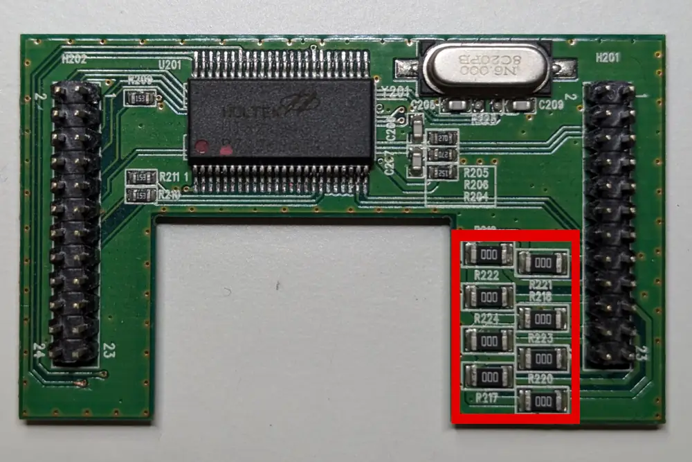
Flip the controller board over, with the pins pointing up, dead-bug style. It should look approximately like this:

On the lower right "leg" of the board, highlighted in the image above, there should be a group of eight surface mount resistors. Using magnification if required, check the numbers on the resistors marked in red on the photo.
-
If the resistors all read "000" and your keyboard has no numeric keypad, you can use the original tenkeyless version of reCODE.
-
If the resistors all read "750" you need the universal / rev-C version of reCODE. (I have only seen this on fullsize models.)
-
If the resistors all read "05L", you are reading them upside down.
-
If the resistors have a different number, you have a version of the keyboard I haven’t encountered. I suggest contacting me before buying to check compatibility.
That’s it!
2. Identifying your version of reCODE
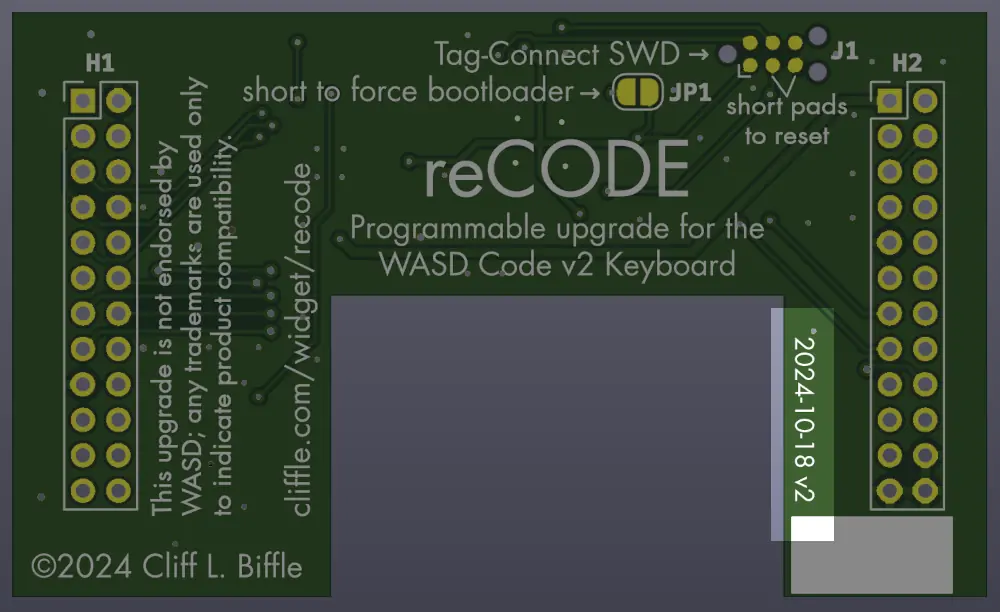
The original, tenkeyless version of reCODE (which I call revision B) has square corners. It’s marked with the text "2024-10-18 v2" on the right hand side as shown on this image:

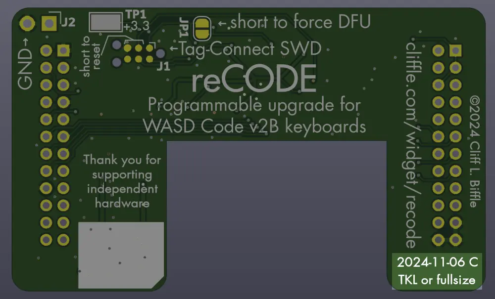
The "universal" revision C board has rounded corners. It’s marked with the text "2024-11-06 C" and the words "TKL or fullsize" on the right hand side as shown on this image:

3. Installation
3.1. Step One: removing the screw(s)
The main screw in the WASD CODE keyboard is hiding behind the circular "OK" warning sticker on the back of the keyboard, in the center. You will need to break through or remove this sticker.
| This sticker is trying to scare you. When you remove it, it will leave behind the word VOID. Voiding a warranty because the device’s owner has opened it has been illegal in the US since the Magnuson-Moss Act in 1975, and is also not permitted in most other countries. So remove that sticker with pride. Remember: if WASD actually supported this keyboard after it was sold, we wouldn’t need to be replacing its printed circuit board ourselves! |
Removing the sticker reveals a cylindrical hole containing a screw. Use a Phillips screwdriver to remove it.
On the tenkeyless keyboard, there is only one screw.
The fullsize keyboard has two more screws, hiding under the lifting feet at the back corners of the keyboard. Squeeze the feet slightly to get them to pop out, which will reveal the screws. Remove them.
3.2. Step Two: removing the top case
The two halves of the plastic case are held together at six points by plastic latches. These latches are now over a decade old, and were not designed for repeated disassembly/reassembly, so it’s hard to get the keyboard open without breaking at least one. Fortunately, they’re redundant, and losing one or two latches doesn’t really affect the feel of the keyboard.
Using a spudger, putty knife, slender flat-head screwdriver, or (if you’re very brave) your fingernail, slide it into the seam along the front of the keyboard below the spacebar, and work it from the center out to the sides. The latches are near the outside corners. It can help to insert your tool at the latch and swivel the handle up, pushing the top of the case in and the bottom of the case out.
This will require a surprising amount of force. Be patient and keep trying.
| Some CODE keyboards only have the external screws, which we’ve already removed, while others use a second screw to secure the keyboard’s metal plate inside the case. Because it’s hard to tell which you have, be careful when finally removing the top case not to dump the keyboard’s innards on the floor. That is, set it on the table and lift the top case off. If you get this wrong you can tear off the USB connector on the back! If your keyboard has the second internal screw securing the metal plate, you do not need to remove it. (I mean, you can if you want. I’m not the cops.) |
3.3. Step Three: removing the controller
With the top case removed, you should see a green or greenish-yellow printed circuit board shaped like an inverted U, wrapped around the cursor keys.
We want to gently lift this out.
The easiest way to do this is to remove the keycaps on the cursor keys and the cluster above them (on an ANSI layout this is delete, end, page down), and then use a spudger or screwdriver to work around the edge of the board and pry it up. Be gentle and try to lift equally around all sides, to avoid damaging the connectors under the board.
Once the controller board is free, set it aside.
3.4. Step Four: soldering the pins
The reCODE kit includes a replacement printed circuit board and two loose rectangular pin headers. You will need to solder these headers to the board for it to work.
There are two options for how to do this. Read both and decide which sounds better to you.
3.4.1. Option 1: install the pins and then solder
The first option is to install the pin headers in the keyboard, put the printed circuit board on top of them, and solder it in place. This makes it much easier to get the alignment right, but also makes it easier to damage your keyboard with a soldering iron. If you choose this option, I suggest removing the keycaps all around the work area so you don’t accidentally melt them.
To solder the pins this way:
-
Take the loose rectangular pin blocks from the reCODE bag.
-
Install one in each black connector on the keyboard, ensuring that the longer side is down (toward the keyboard), and that all pins are in the connector rather than hanging off to one side.
-
Take the reCODE PCB and line up its holes with the pins, so that it drops fully into place. The side of the board facing you should have lots of words and no chips.
-
Solder all the pins. (I suggest starting with the outside corners, to hold the PCB in place as you work.)
| Even if you choose to solder the PCB in-place, you can still remove it to reverse the upgrade after the solder cools. |
3.4.2. Option 2: solder separately and then install
The second option is to install the pin headers separately on your work surface, and then install the assembled PCB. This lets you do the soldering far away from your precious keyboard, avoiding potential key-melting. I think this option winds up being more work overall, but if you’re concerned about your ability to wield a soldering iron without accidentally melting things, this may be more comfortable for you.
-
Put a heat-resistant object on your work surface. A ceramic drink coaster works great.
-
Take the two blocks of rectangular pins and the PCB from the reCODE bag, and slot the short side of the pins into the PCB. Make sure they sit on the side that reads "HEADERS ON THIS SIDE" (revB) or "SOLDER ON OTHER SIDE" (revC).
-
Carefully flip the assembly over so that the long pokey ends of the pins are against your heat-resistant surface. (A little bit of tape to hold things together during assembly might help.)
-
Solder all the pins. (The side of the board facing you at this point should have no chips on it.)
-
Once the solder is solid, transfer the assembled board to your keyboard, carefully lining up the pins.
| It’s easy to mis-align the board at this point, by accidentally offsetting the pins in the keyboard’s connectors. Before pressing down, look around the sides of the board to make sure that the shiny metal pins are all resting in the black connectors beneath, and are not hanging next to the connector. If the board is aligned properly, the gaps around it when seen from above should be approximately even on all sides. |
Once you’re confident in the alignment, press gently down on both groups of pin headers until reCODE is fully seated.
3.5. Step Five: test
| I recommend doing this before you reinstall the plastic shell on the keyboard, just in case something is wrong! |
Connect the keyboard to a computer using an appropriate USB cable.
Mash some keys. If all is well, the keys should do stuff.
If it doesn’t work, unplug the keyboard promptly and check the alignment of the reCODE PCB in the connectors on the keyboard.
If the alignment looks right, check that the solder on all pins appears to have flowed properly.
If the solder looks good, and it still doesn’t work, contact me.
4. Using QMK
QMK is the de-facto standard hackable keyboard firmware among enthusiasts, and to keep my support burden down, I ship reCODE with QMK installed. By default, I’ve configured a keymap that is designed to roughly match the original behavior of the CODE keyboard, controlled by the DIP switches on the back. The DIP switches are numbered starting from 1 at the left to 6 at the right.
DIP switches 1 and 2 control the base keyboard layout:
-
1 off + 2 off = QWERTY with PC/ANSI modifier key order.
-
1 ON + 2 off = QWERTY with Mac modifier key order.
-
1 off + 2 ON = Dvorak with PC modifier key order.
-
1 ON + 2 ON = Colemak with PC modifier key order.
DIP switch 3, when ON, changes the CapsLock key to a second Left Control key, without affecting the behavior of the Left Control key.
DIP switch 4, when ON, replaces the ScrollLock key with a "Winkey Lock," which toggles whether the Windows/Super/GUI keys do anything. Apparently this is useful for gaming because Windows does something annoying when you tap these keys by accident.
DIP switch 5, when ON, changes the default state of the Windows/Super/GUI keys to disabled. If DIP switch 4 is also ON, you can enable them by tapping ScrollLock; otherwise, you just won’t have Windows keys. (This is different from the original WASD behavior, where DIP switch 5 effectively disables switch 4.)
DIP switch 6, when ON, converts the Menu key (next to Right Control) into a Function key. This enables access to another key layer:
-
Fn-Ins is Play/Pause
-
Fn-Home is Stop
-
Fn-Del is Previous Track
-
Fn-End is Next Track
-
Fn-PageUp is Volume Up
-
Fn-PageDown is Volume Down
-
Fn-Pause is Mute
-
Fn-Print is Eject (requires Mac mode on WASD, enabled by default on QMK)
-
Fn-F12 toggles the backlight
-
Fn-F11 cycles betweeen backlight brightness levels
-
Fn-ESC reboots the keyboard into DFU mode for reflashing (added for QMK)
4.1. Building it yourself
QMK support for reCODE is currently not merged upstream, which means if you want
to build it yourself, you’ll need to build from
my fork. (Make sure to check out the
recode branch.)
Concretely:
-
Install the QMK tools. If you haven’t worked with QMK before, follow their getting-started guide.
-
Add my fork to your QMK checkout with
git remote add recode https://github.com/cbiffle/recode-qmk/ -
Checkout the recode branch:
git checkout recode/recode -
Build and flash appropriate image:
-
Tenkeyless (original) boards:
qmk flash -kb cbiffle/recodev2tkl -km default -
Universal (rev-C) boards:
-
In a tenkeyless keyboard:
qmk flash -kb cbiffle/recode_revc -km tkl_ansi -
In a full-size keyboard:
qmk flash -kb cbiffle/recode_revc -km fullsize_ansi
-
-
At the end of the build, qmk will try to flash the image onto the keyboard.
This requires you to put the keyboard into DFU mode. There are two ways to do
this:
-
Unplug the keyboard, hold down the ESC key, and plug it in while still holding ESC.
-
If you have enabled the Fn key (dip switch 6 is ON), press Fn-ESC to reboot the keyboard without unplugging it.
Note that once you do this, your keyboard will stop being a keyboard until flashing is complete. You might want to have a backup on hand, just in case.
5. Using Keybrain
| Upstream Keybrain only supports the tenkeyless version of reCODE for now. |
Keybrain is a from-scratch implementation of a USB HID keyboard, written in Rust. I wrote it while developing reCODE, because I wanted to understand exactly how all the moving parts work.
QMK is very powerful, but its convenience features can make it hard to understand how everything fits together. Its repository contains well over one million lines of C code, so it’s impossible for one person to read it all.
Keybrain is much less powerful, but consists of 1,400 lines of Rust with no significant external dependencies or operating system. It’s designed to be understood completely, and hacked on, by a single person.
If you’re curious, have a look at the repository.
| Keybrain works well, and I’ve been using it daily for four years. However, it’s not as easy to configure as QMK. If you’re excited about digging into the details of how a keyboard works, or not excited about using C, then Keybrain may be what you’re looking for! For most users, QMK is the right choice. |
6. Reflashing the manufacturing image
If you’d like to reset the firmware to what I shipped (say, for
troubleshooting), it’s linked at the bottom of this document. I recommend
downloading the DFU version. You will need the dfu-util command line program,
which you can get from QMK toolbox, or install separately.
Put the keyboard into DFU mode using one of the following methods:
-
If you have enabled the Fn key using DIP switch 6 or a custom layer, press Fn-Esc.
-
Hold ESC while plugging in the keyboard.
-
If the keyboard is unresponsive, follow the directions in the next section.
Now run the command:
dfu-util -D FILENAME.dfu -R
…where FILENAME should be replaced with the name of the image you
downloaded. The manufacturing images are all linked at the end of this manual.
Note that you may need to unplug/replug the keyboard to get it to wake up after reflashing.
7. Recovering from bad firmware
| If all you want to do is update the firmware, you can access DFU mode by either holding ESC while plugging the keyboard in, or (if you have enabled the Fn key using the DIP switches or a custom layer) pressing Fn-Esc. The method described here is for emergencies. |
If flashing fails, or if the firmware is so buggy that you can’t get back to DFU mode, you can force DFU mode in hardware:
-
Remove the top plastic shell of the keyboard (sorry) to expose the controller PCB.
-
Unplug the keyboard.
-
Using a pair of metallic tweezers, the end of a screwdriver, or a random piece of metal, short across the two pads labeled "JP1, short to force bootloader."
-
While holding that, plug the keyboard in.
The keyboard should come up in DFU mode.
8. Using a debugger
reCODE has a TagConnect-compatible SWD footprint on its top side. You can use this to connect a SWD debugging interface such as an STLink. The easiest way to do this is by buying a TagConnect 2030 to SWD adapter cable, but you could solder wires to the pads in a pinch.
9. Downloads and odds and ends
-
Schematics:
-
Manufacturing firmware images:
-
revB (TKL-only):
-
in DFU format (easiest)
-
in BIN format (most general)
-
in ELF format with symbols (for debugging)
-
-
revC (universal):
-
Tenkeyless keymap:
-
in DFU format (easiest)
-
in BIN format (most general)
-
in ELF format with symbols (for debugging)
-
-
Fullsize keymap:
-
in DFU format (easiest)
-
in BIN format (most general)
-
in ELF format with symbols (for debugging)
-
-
-